The given SIMULINK model compare the performance of the same block with and without zero-vector manipulation. The derivation of pulse width control laws is given in zipped Excel files. To enable this manipulation, the SVPWM block needs to receive the NPV fluctuation signal and the three-phase currents. The splitting of T0 between vectors O111 and O000 can be manipulated in favor of suppressing the neutral point voltage fluctuation since each vector has the same effect on the pole voltage but opposite effects on the neutral point voltage. This time is implemented by allocating it using the zero vector O111 in the middle of the pulses and O000 on both edges. It is the manipulation of the time assigned for the zero-vector. In this contribution, another suppression method is combined with the previous one. In the previous contribution, the suppression technique is limited to the swapping of redundant vectors. The author of this contribution has previously contributed an algorithm that doesn't exploit the possibilities for suppressing the neutral point fluctuation. 1933-1942, May 2008, doi:10.1109/ SVPWM technique is the most suitable one for encoding onto DSP and microcontrollers since these devices have suitable dedicated H/W resources that can receive slow rate updates of the duty cycle (for example at 50 to 100 microseconds) and produce very fine PWM resolutions using their integrated capture compare H/W modules. Freijedo "Multilevel Multiphase Space Vector PWM algorithm", IEEE® Transactions on Industrial Electronics, vol. Oscar Lopez, Jacobo Alvarez, Jesus Doval-Gandoy and Francisco D. The output voltage of the inverter 'Vout' has five levels in phases b, c, and d (k=2,3,4) and three levels in phase a and e (k=1,5). Therefore, the modulation is working properly. This paper presents simulation and analysis of vector control scheme of PMSM using SVPWM inverter. The filtered output voltage 'filtered Vout' of the converter follows the reference voltage 'Vref'. The phase shown in the scope can be selected by means of the 'Phase selection' block. 'Vout(k)' is the switched output voltage of phase 'k'. 'filtered Vout' is the output voltage of 'Vout' phase after been filtered with a low-pass filter. 'Vref' is the sampled voltage reference for each phase. Load neutral is connected to the inverter neutral.
#Svpwm matlab simulink series#
The loads are resistances with a series connected inductances. To enable this manipulation, the SVPWM block needs to receive the NPV fluctuation signal and the three-phase currents. DEVELOPMENT OF MATLAB SIMULINK MODEL FOR SVPWM WITH UNDER-MODULATION REGION 1 Introduction This report focuses on DC to AC power inverters, which aim to efficiently transform a DC power source to a high voltage AC source, similar to power that would be available at an electrical wall outlet. The '5-level 5-phase cascaded full-bridge inverter' block is the ideal model of the multilevel voltage-source converter.ħ.


All solved numerical examples have been retained, and the 10 MATLAB®Simulink® programs remain online. The simulation and experimental results proved the proposed scheme.

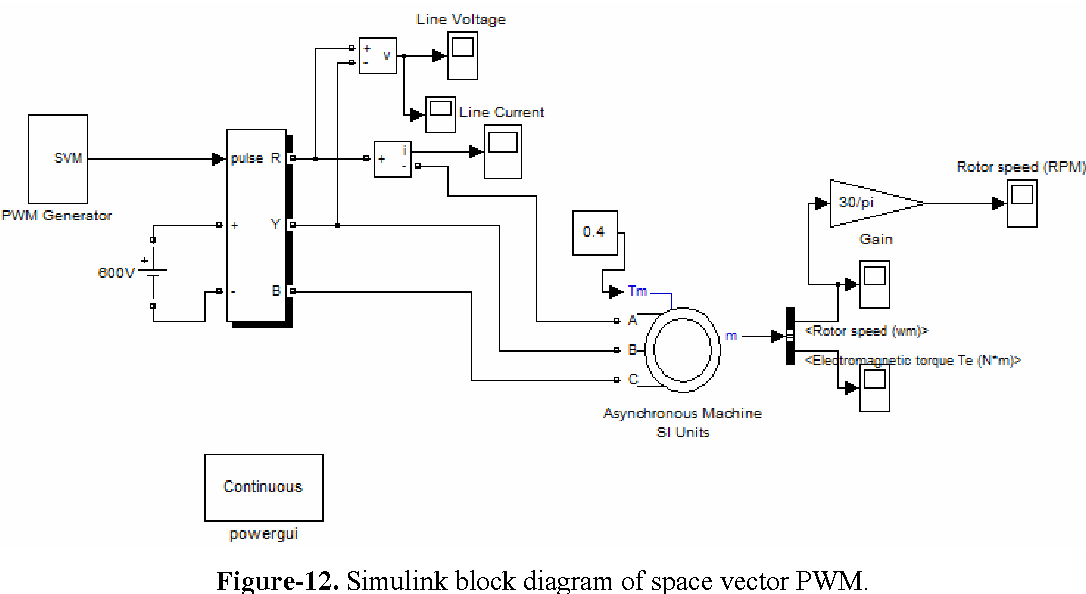
The 'Trigger signals' generates the proper trigger signals from output levels specified in each switching vector.Ħ. Using Svpwm Technique drives, have been added as have two new chapters on advanced scalar control and multiphase electric machine drives. the proposed SVPWM was simulated in MATLAB/SIMULINK. The 'Sequence' block provides the time sequence of switching vectors.ĥ. Both blocks require the specification of the number of phases and their outputs are a matrix with the switching vector sequence and a vector with the switching times.Ĥ. This block makes use of the block 'Two-level multiphase SVPWM', also described in, that can be used alone with two-level multiphase converters. The 'Multilevel multiphase SVPWM' performs the multilevel multiphase space-vector PWM (SVPWM) algorithm presented in. The 'Normalize' block normalize the reference voltageģ. The 'Sine Wave f' and 'Fifth harmonic' blocks generate an unbalanced five-phase reference voltage with a fifth harmonic.Ģ. Detailed information about the modulation algorithm, its Simulink® implementation, and the simulated case can be found in. It includes a five-level five-phase inverter feeding a passive load. MATLAB/SIMULINK IMPLEMENTATION AND ANALYSIS OF THREE PULSE-WIDTH-MODULATION (PWM) TECHNIQUES by Phuong Hue Tran. This example shows the operation of the Multilevel multiphase SVPWM and Two-level multiphase SVPWM.


 0 kommentar(er)
